


Phone:
+86-13598092101


Dec 23, 2025

 Vertical Sterilizer Tank
 Sterilizer Hydraulic Door
 Horizontal Type Sterilizer Tank
 Transfer Carriage
 Palm Fruit Cage
 Tippler
 Palm Fruit Twin Screw Press
 Palm Kernel Expeller
 Empty Palm Fruit Bunches Press
 Thresher Drum
 Digester
") Palm Nut Crusher(Ripple Mill)
Palm Nut Crusher(Ripple Mill)
 Nut Polishing Drum
 Palm Kernel & Shell Separate Winnowing System
 Palm Kernel & Shell Separate Hydraulic System
 Clay Bath
 Air Lock
 Nut Grading Screen
 Vertical Oil Clarifier Setting Tank With Stirrer
 Palm Kernel Dryer
 Fiber Cyclone
 Scraper Conveyor
 Screw Conveyor
 Bucket Elevator
 Back Pressure Vessel
 Palm Kernel Storage Bin
 Palm Nut Hopper
 MBR Water Treatment System
 Hard Bunch Shredder
 Double Deck Circular Vibrating Screen
 Pressure Leaf Filter
 Palm Shell & Kernel Caly Bath Seperator
Palm Kernel Expeller
Palm Kernel & Shell Separate Winnowing System
Palm Kernel & Shell Separate Hydraulic System
Nut Grading Screen
Palm Kernel Dryer
Bucket Elevator
Palm Kernel Storage Bin
Palm Nut Hopper
Pressure Leaf Filter
Palm Shell & Kernel Caly Bath Seperator
Palm Kernel Expeller
Palm Kernel & Shell Separate Winnowing System
Palm Kernel & Shell Separate Hydraulic System
Nut Grading Screen
Palm Kernel Dryer
Bucket Elevator
Palm Kernel Storage Bin
Palm Nut Hopper
Pressure Leaf Filter
 Extruder
 Process Water Tank
 Condensate Water Tank
 Ring-Type Extractor
 Vertical Extraction Unit
 Extraction Unit") Horizontal (Plate Chain) Extraction Unit
Horizontal (Plate Chain) Extraction Unit
 Desolventizer DTDC
 Solvent Evaporator for Mixed Oil Extraction
 Vibrating Cleaning Screen
 Submerged Arc Scraper Conveyor
Vertical Sterilizer Tank
Submerged Arc Scraper Conveyor
Vertical Sterilizer Tank
 Membrane Press Filter
 Degassing Tower
 Deodorization Tank
 Fatty Acid Distillation Tower
 Fatty Acid Heavy & Light Phase Distillation Column
 Sweet Water Setting Separation Tank
 Foam Trap
 Degumming Tank
 Decolorization Tank
Process Water Tank
Condensate Water Tank
Decolorization Tank
Process Water Tank
Condensate Water Tank
 Hydrolysis Tower
 Tubular Heater
 Fatty Acid Heater
 Atmospheric Leg Pool
 Fatty Acid Flash Separation Tank
Crystallization Tank
Fatty Acid Flash Separation Tank
Crystallization Tank
 Shell and Tube Heat Ex-changer Vessels
 Sweet Water Flash Separation Tank
 Glycerin Evaporator
 Glycerol Residue Stripper
 Crude Glycerol Heater
 Glycerol Gas Condenser
 Glycerin Buffer Tank
 Glycerin Distillation Tower
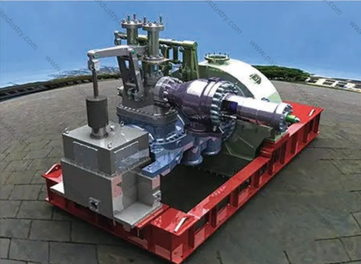
Extraction condensing steam turbine are single-cylinder, single-shaft impulse types with a single-stage regulating extraction. The unit's industrial extraction volume and electrical load can be automatically adjusted according to user requirements, and pure condensing operation is also permitted. All units in this series consist of rotor and stator components. The rotor adopts a sleeve-type structure, while the stator includes the cylinder, nozzles and baffles, labyrinth steam seals, bearings, and other parts. The high-medium cylinder lift plate-type regulating steam valve is mechanically linked to the hydraulic motor of the speed control system via levers. This series supports fully hydraulic speed control systems, imported governors, electro-hydraulic converters, automatic high-speed extraction devices, and various safety components and monitoring instruments. Single-extraction steam turbine. Composed of high-pressure and low-pressure sections, it functions as a combination of a back-pressure turbine and an extraction turbine. Fresh steam enters the high-pressure section to perform work. After expanding to a certain pressure, it splits into two streams: one is extracted to supply heat users, while the other enters the low-pressure section for further expansion and work before being discharged into the condenser.
| Model | Power (MW) | Intake Parameters | Vacuuming Parameters | Gas Consumption Rate | Exhaust pressure (Mpa) | Size (mm) | Electric motor (mm) | ||||
| Press (MPa) | Temp (℃) | GFR (t/h) | Press (MPa) | Temp (t/h) | Rated (kg/kw.h) | Condensation (kg/kw.h) | |||||
| C1.5-2.35/0.490 | 1.5 | 2.35 | 390 | 17.8 | 0.49 | 12 | 11.87 | 5.89 | 0.008 | 3475×2060×2100 | 6500L/1500R |
| C1.5-2.35/0.78 | 1.5 | 2.35 | 390 | 18.4 | 0.78 | 12 | 12.27 | 5.9 | 0.008 | 3475×2060×2100 | 6500L/1500R |
| C1.5-2.35/0.981 | 1.5/1.5 | 2.35 | 390 | 19.6 | 0.981 | 12/15 | 13.07 | 5.932 | 0.0079 | 4320×2560×2830 | QFC-1.5-2 |
| C1.5-3.43/0.490 | 1.5/1.5 | 3.43 | 435 | 16.1 | 0.49 | 12/15 | 10.73 | 5.6 | 0.0075 | 4238×2560×2663 | QF-1.5-2 |
| C3-2.35/0.490 | 3/3.3 | 2.35 | 390 | 27.1 | 0.49 | 18/20 | 9.03 | 5.12 | 0.0075 | 4268×2552×2822 | QF-3-2 |
| C3-2.35/0.981 | 3/3.3 | 2.35 | 390 | 34.3 | 0.981 | 20/25 | 11.43 | 5.42 | 0.007 | 4320×2550×2823 | QF-3-3 |
| C3-3.4310.294 | 3/3.3 | 3.43 | 435 | 25.3 | 0.294 | 19/23 | 8.43 | 474 | 0.0075 | 4320×2558×2830 | QF-3-2 |
| C3-3.43/0.490 | 3/3.3 | 3.43 | 435 | 25.8 | 0.49 | 20/25 | 8.60 | 4.68 | 0.0073 | 4268×2550×2825 | QF-3-2 |
| C3-3.43/0.785 | 3 | 3.43 | 435 | 28 | 0.785 | 20/25 | 9.33 | 4.74 | 0.0073 | 4310×2558×2829 | QF-3-2 |
| C3-3.43/0.981 | 3/3.3 | 3.43 | 435 | 29.3 | 0.981 | 15/19 | 9.77 | 4.748 | 0.0072 | 4320×2558×2830 | QF-3-2 |
| C3-3.43/1.37 | 3/3.4 | 3.43 | 435 | 30.2 | 1.37 | 20/25 | 10.07 | 4.79 | 0.0068 | 4296×2558×2455 | QF-3-2 |
| C3-3.43/1.77 | 3/3.3 | 3.43 | 435 | 27.35 | 1.77 | 15/20 | 9.12 | 4.62 | 0.0071 | 4268×2558×2830 | QF-3-2 |
| C3-4.9/1.27 | 3 | 4.9 | 470 | 33.7 | 1.27 | 25/30 | 11.23 | 4.79 | 0.0049 | 4700×2570×2825 | QF-3-2 |
| C6-2.35/0.490 | 6 | 2.35 | 390 | 52.15 | 0.49 | 34/50 | 8.69 | 5.2 | 0.0071 | 4248×2558×2450 | QF-6-2 |
| C6-3.43/0.490 | 6/6.6 | 3.43 | 435 | 53.7 | 0.49 | 45/56 | 8.95 | 4.6 | 0.0071 | 4268×2560×2830 | QF-6-2 |
| C6-3.43/0.589 | 6 | 3.43 | 435 | 50.3 | 0.589 | 35/55 | 8.38 | 4.68 | 0.0071 | 4248×2813×2258 | QF-6-2 |
| C6-3.43/0.785 | 6 | 3.43 | 435 | 59.1 | 0.785 | 45/55 | 9.85 | 4.65 | 0.0068 | 4248×2813×2258 | QF-6-2 |
| C6-3.43/0.981 | 6/6.6 | 3.43 | 435 | 61.8 | 0.981 | 45/56 | 10.30 | 4.7 | 0.0073 | 4248×2558×2830 | OF-6-2 |
| C6-3.43/1.27 | 6/6.6 | 3.43 | 435 | 64.08 | 1.27 | 45/60 | 10.68 | 4.663 | 0.0073 | 4296×2560×2450 | QF-6-2 |
| C6-3.43/1.57 | 6 | 3.43 | 435 | 65.3 | 1.57 | 45/60 | 10.88 | 4.61 | 0.007 | 4296×2560×2450 | QF-6-2 |
| C6-4.90/0.490 | 6/6.6 | 4.9 | 435 | 50 | 0.49 | 40/45 | 8.33 | 4.54 | 0.006 | 4813×2705×2455 | QF-6-2 |
| C6-4.90/0.785 | 6 | 4.9 | 470 | 41.18 | 0.785 | 30/40 | 6.86 | 4.3 | 0.0053 | 4785×2705×2458 | QFW-6-2 |
| C6-4.90/0.981 | 6/6.6 | 4.9 | 435 | 51 | 0.981 | 34/45 | 8.50 | 4.57 | 0.006 | 4813×2705×2458 | QF-6-2 |
| C6-4.90/1.76 | 6 | 4.9 | 435 | 53.13 | 1.76 | 30/40 | 8.86 | 4.98 | 0.005 | 4725×2705×2458 | QF-6-2 |
| C6-4.90/2.45 | 6 | 4.9 | 435 | 66.3 | 2.45 | 45/50 | 11.05 | 4.54 | 0.005 | 4880×2705×2575 | QF-6-2 |
| C7-3.4310.490 | 7 | 3.43 | 435 | 53.3 | 0.49 | 35/45 | 7.61 | 4.58 | 0.0057 | 4268×2558×2458 | QF-7-2 |
| C7-3.43/0.785 | 7 | 3.43 | 435 | 56.7 | 0.785 | 35/45 | 8.10 | 4.6 | 0.007 | 4374×2558×2458 | QF-7-2 |
| C7-3.43/1.27 | 7 | 3.43 | 435 | 42 | 1.27 | 11/20 | 6.00 | 4.6 | 0.007 | 4296×2812×2258 | QF-7-2 |
| C7.5-3.43/0.490 | 7.5 | 3.43 | 435 | 61.3 | 0.49 | 45/55 | 8.17 | 4.65 | 0.007 | 4250×2558×2452 | QF-7.5-2 |
| C7.5-3.43/0.981 | 7.5 | 3.43 | 435 | 68 | 0.981 | 45/56 | 9.07 | 4.59 | 0.0062 | 4375×2558×2458 | QF-7.5-2 |
Configuration: Quick-assembly multi-stage steam turbine
Arrangement: Double-deck
Mechanical Speed Control: Fully hydraulic regulation
Electronic Speed Control: Electro-hydraulic converter governor, integrated control system comprising four major systems (governor, control, detection, protection)
Overspeed Protection: Mechanical fly-hammer protection with electromagnetic valve electronic intelligent control
Steam Seal Type: Stainless steel labyrinth steam seal, honeycomb contact steam seal
Main Steam Valve: Integrated automatic main steam valve (combination valve with quick-closing regulation)
Main shaft assembly: Restart stage rotor blades, interference fit between rotor and rotor blades
Lubrication system: Oil lubrication (with integrated lubrication station)
Thermal expansion compensation: Sliding thermal compensation for front bearing support
Electrical configuration: Complete set of electrical control cabinets, protection cabinets, main control cabinets, with domestic generator (voltage 400-6300- 10050V)
Turbine Turning Method: Manual or Electric
The design extraction pressure is determined based on thermal user requirements and controlled by a pressure regulator to maintain stable extraction pressure. The power output of a single extraction steam turbine is the sum of power generated by the high- and low-pressure sections, determined by the steam inlet volume and the steam flow through the low-pressure section. Adjusting the steam inlet volume allows for different power outputs. Therefore, within a certain range, both thermal and electrical load requirements can be simultaneously met. When the heat extraction steam flow is zero, a single extraction steam turbine functions as an extraction condensing turbine. If all steam entering the high-pressure cylinder is extracted for heat users, it operates as a back-pressure turbine. However, in actual operation, a certain amount of steam must flow through the low-pressure section into the condenser to cool the low-pressure cylinder and dissipate heat generated by friction losses. The minimum required flow rate isapproximately 10% of the low-pressure cylinder's design flow rate.
